State Machine Diagrams
What
State Machine Diagrams for selected classes
How
The Dish
State Machine Diagrams for selected classes.
Ingredients
Process
From the Class Event Table identify the classes with events.
For each class consider the complexity of the states which the objects have to go through.
For classes with more states draw a state machine diagram for each class.
When drawing a state machine diagram, you should first identify the creation state and then whether any final states exist. After this, ask what other states it passes through in the life cycle of an object? Often states can be found by looking at the boundary values of the attributes.
After having defined the states, find the events that trigger the transition from one state to another. In each state ask which events can bring the object out of this state?
Expect to redraw the state diagrams several times during the analysis. It is therefore recommended to use a drawing tool to facilitate the process. There are a lot of different programmes available ranging from simple drawing tools to full blown case tools that are able to produce code from the diagrams.
How in detail
To be able to remember the events in the problem domain, the class needs attributes to store the information that was registered with an event. Only major attributes are added to the class in this state. Trivial attributes are postponed for later processes.
Diagram elements
Basic State Machine Elements
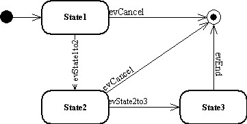
The arrow with an event written on the line is an event or a transition. Generally, processing is done on the event. In a state (shown below) usually nothing happens in the object - though it is a possibility to have entry or exit .
States and events (or transitions)
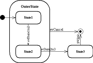
As seen in the example above the evCancel is common to State1 and State2. A better way to solve this is to introduce a superstate as seen in the figure below.
Alternative diagram
The above example shows the same situation as the diagram with the superstate. evCancel will now regardless whether the object is in State1 or State2 bring the object into the Final State.
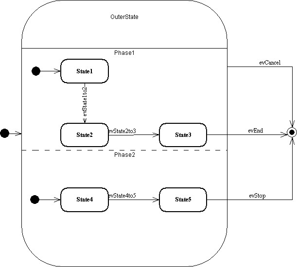
Concurrent Substate
The above example shows a special situation, where states 1-3 and states 4 and 5 should work concurrently - in separate threads. As a consequence any event in Phase1 will trigger a transition from one state to another in Phase1, just as any event in Phase2 will trigger transition from one state to another in Phase2. This occurs independently. Please note that evCancel still forces the transition to the final state regardless of which state the two phases are in.
In state machines, the event(s) shown leaving a state is the only legal event that can bring the object from that particular state to the next state. All other events legal for other states in the object are ignored. If, for instance, the object is in State2 as shown above, the only legal event to accept is evState2to3. If, for instance, evEnd occurs the event is ignored.
Conditionals
Conditionals can be drawn with a diamond as shown above or a filled circle. The branches should have the conditions written in sharp brackets. Finding the states
When drawing a state machine diagram, you should first identify the creation state and then whether any final states exist. After this, ask what other states it passes through in the life of an object? Often states can be found by looking at the boundary values of the attributes.
After having defined the states, find the events that trigger the transition from one state to another. In each state ask which events can bring the object out of this state?
Expect to redraw the state diagrams several times during the analysis. It is therefore recommended to use a drawing tool that facilitates the process. There are a lot of different programmes available ranging from simple drawing tools to full blown case tools which are able to produce code from the diagrams.
Why
State diagrams - or as denoted in UML 2 State Machine Diagrams - describe the dynamics or the behaviour of a class. Many classes react on the exterior events described earlier in the Class - Event Table. The sequence diagrams express the dynamics in the system, i.e. the interaction between objects.
The objects reflect the problem domain and as a consequence of this, the objects also reflect the behaviour and states a problem domain object undergoes. The object should remember the problem domain states.
Remember that mechanical parts, electronic hardware parts as well as software parts can have states during its operation.
Example
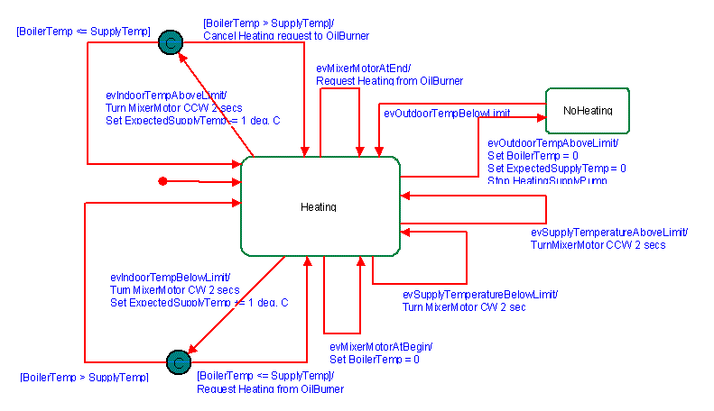
 An example of a State Machine Diagram for the class BoilerUnit.
Used In
The State Machine Diagrams are used during the realisation of the system-to-be and especially in Class Design.
If you are following the guide strictly you may want to go to Use Case Analysis from here.


