Use Case Scenarios
Contents
What
Sequence diagrams for modelling how objects interact with each other.
How
The dish
Detailed Sequence Diagrams
Ingredients
- The selected use cases for the current iteration
- Sequence diagrams produced in the Launch phase
Process
In the Design phase, you must focus on delivering the functionality for the current iteration. You have to identify the objects taking part in order to deliver the functionality and the interaction between the objects. Now you can draw one or more sequence diagrams that model the dynamics. Typically, you will pick one or more use cases when choosing the functionality for a given iteration and then produce a sequence diagram for each use case scenario.
The sequence diagrams produced earlier in the development process are refined and prepared in more detailed versions. In this way, you will dive into the details of the dynamics of the system-to-be. The level of details should be somewhere between the level of details provided by the sequence diagrams in the Launch phase and the details of the actual implementation.
How in detail
General introduction to drawing sequence diagrams
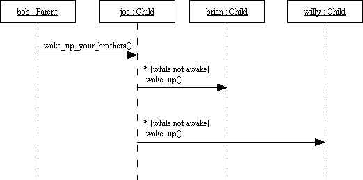
Draw a rectangle at the top of the diagram for each object participating in the process that you want to model. Each rectangle should be labelled with the name of the object and the name of the class separated by a colon - the object name is optional. Now draw a vertical line - the so-called lifeline - below each object.
The first message sent is modelled by a horizontal arrow from the lifeline of the sender to the lifeline of the receiver. The arrow is labelled with the name of the message and the names of the parameters and the return value. The next message sent is modelled by adding a new labelled arrow below the first one. In this way, you can read a sequence diagram from top to bottom.
You can add a condition to the message that must be satisfied for the message to be sent. It is also possible to indicate that a message is iterated by using an asterisk - '*'.
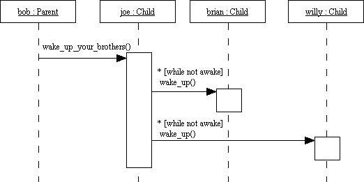
Optionally, you can illustrate that an object is busy answering a message by so-called activations. Activations are rectangles drawn on the lifelines in the following way:
Why
The sequence diagrams produced in the Design phase are the sketches to use in the Implementation phase. The developer implementing the functionality for the current iteration must have a clear idea of how to implement the functionality before the actual implementation takes place.
Example
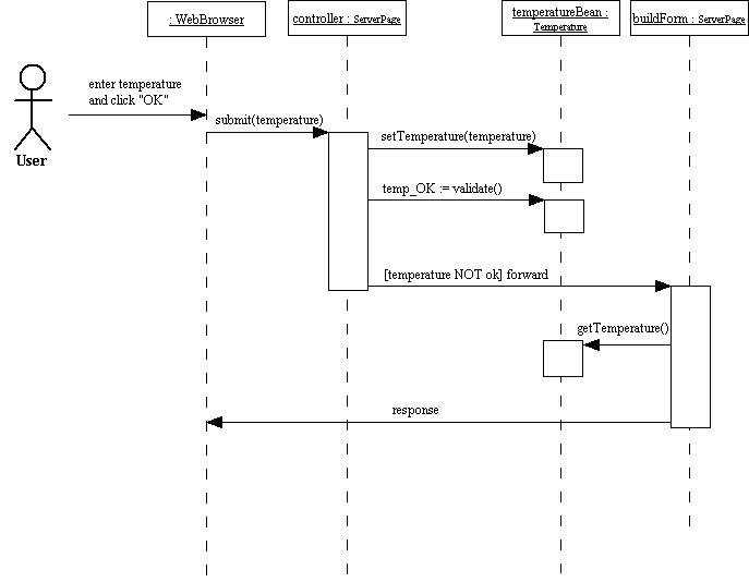
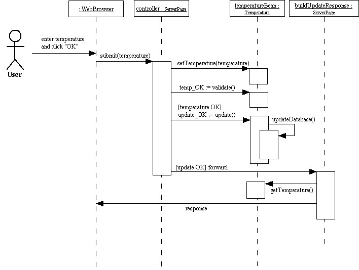
Now let us turn to the system that should regulate the temperature in a house in accordance with the user's wishes. The following two diagrams show how a temperature entered by the user could be processed. The first diagram illustrates what happens if the temperature entered is not valid. The second diagram shows the process for a valid temperature.
The user enters the temperature in a web-browser and the temperature is submitted to a controller on the server. The controller sets the temperature on a temperature object and asks this object to validate itself. The controller tells another server page to take over, if something is wrong with the temperature - the new server page is responsible for building a form and present it to the user so the user can correct the temperature.
The controller tells the temperature object to update itself if the temperature is valid, and the temperature object performs some operations in order to update the database. The controller forwards the request to another server page if the update succeeds. The new server page is responsible for informing the user about the success of the update.
Block Diagram Design is the next page.


