Difference between revisions of "Blockdiagram"
From EUDP
(Created page with "A blockdiagram, as the name implies, contains blocks. Before drawing a blockdiagram, one needs an overview of the required functionality in the collection of blocks (that wou...") |
|||
| Line 19: | Line 19: | ||
{| class="wikitable" | {| class="wikitable" | ||
|- | |- | ||
| − | ! [[File:bd1.png|300px] !! [[File:bd2.png|300px]] !! [[File:bd3.png|300px]] | + | ! [[File:bd1.png|300px]] !! [[File:bd2.png|300px]] !! [[File:bd3.png|300px]] |
|} | |} | ||
Revision as of 11:06, 27 August 2012
A blockdiagram, as the name implies, contains blocks.
Before drawing a blockdiagram, one needs an overview of the required functionality in the collection of blocks (that would be the system-to-be).
The principal parts or functions, in the system-to-be, are represented by blocks connected by lines, that show the relationships of the blocks.
Block diagrams can represent both Hardware, Software or Mechanical engineering.
In order to draw a block diagram, follow these simple rules :
- Name blocs meaningfull
- Inputs are on the left, outputs are on the right
- Higher abstraction are on top, lower in the bottom, it this is possible to distinguish
- For example physical hardware blocks will be drawn in the bottom, and the user application will drawn on the top
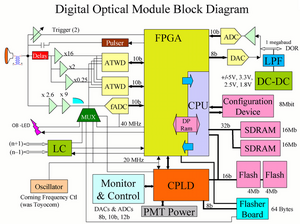
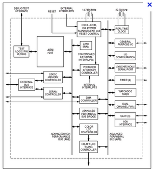
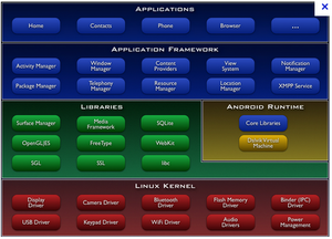
A few examples:
 |
 |

|
|---|