Class Diagram
What
Description of each class' responsibilities and a Class Diagram
How
The Dish
Description of each class and Class Diagram
Ingredients
Process
For each class in the Class Event Table write a short description with the main responsibilities for the class.
Look for generalizations.
Associate, aggregate or make compositions between related classes.
Assemble classes with a natural relationship into packages.
How in details
The class diagram is a composition of the business model. The business model represents the Problem Domain, which is the part of the world we want the system-to-be to control.
Modelling the class diagram is not an easy task, and it is more the rule than the exception that you return to the candidates and delete or add some.
Describe the classes
The best way to start the modelling work is to give a short description of each class in the Class Event Table. Describe in a few sentences what the class responsibilities are. By describing the class you achieve a better knowledge of the class.
Generalisations
Next task is to look at the Class Candidates and find classes that are similar. Analyse the similar classes and if there are common parts, then consider to create a superclass. A superclass is a class that implements the common parts of subclasses. A superclass implementation is inherited to subclasses.
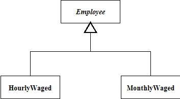
Example: Employees may receive wages on an hourly basis or on a monthly basis. Two types of employees have a lot of common features; Name, address, bank account, social security number, department, etc. But there are also some differences. In this example the hourly paid employees will receive a pay check every 14 days, whereas the monthly paid employees will receive a pay check at the end of the month. From this we can see that a superclass Employee can implement the common parts, i.e. name, address, etc., and routines for handling this information. In the subclasses only the differences are implemented. In this example it is the calculation of the wages that is based on different rules.
Formally, the superclass - subclass construction is called a generalisation. A generalisation is drawn by placing the superclass in top of the diagram. A line with an arrow points towards the superclass. The subclasses are placed below the superclass. See the example below:
The direction of the arrow can be difficult to understand for newcomers. But you should read the diagram from the bottom: Subclasses unite the common parts in the superclass.
Please note: Usually when composing the initial class diagram, only squares with no internal dividers are drawn. The name of the class is written in the box. If there are no objects of a class, the name is written in italics (an abstract class). In the above example there are no objects of the superclass Employee. There are only objects of the subclasses. A superclass is also often called baseclass. (More experienced developers may draw a full class with important attributes and methods listed.)
In the above example there were two subclasses. This is not always the situation. Sometimes only one subclass is seen. This leads to the definition of a generalisation:
Class A is a generalisation of class B if and only if:
- every instance of class B is also an instance of class A; and
- there are instances of class A which are not instances of class B.
Equivalently, A is a generalisation of B if B is a specialisation of A.
This leads to the definition of a specialisation:
Class B is a specialisation of class A if and only if:
- every instance of class B is also an instance of class A; and
- there are instances of class A which are not instances of class B.
Let us look at an example: We have the two classes Vehicle(A) and Car(B). The car is a vehicle, but the vehicle is not necessarily a car - it can be a truck. The vehicle class contains all that describe vehicles in general and the car class specialises this by declaring that it can carry passengers.
Associations, aggregations and compositions
Associations, aggregations and compositions can be used to interconnect objects in the problem domain. Associations, aggregations and compositions describe the relations between the classes. Where aggregations and compositions describe a tight relation, the associations describe a more loose relation.
Definition:
- Association: a very loose relationship, which might even be rather short-term and changing.
- Aggregation: whole-part, a medium or typically long-term relationship.
- Composition: whole-part, a strictly defined lifetime relationship.
Associations can be identified by looking at the relationship between two classes. If keywords like the following can be used, it is an association: Connected (to), associated (to), related (to), knows a ... .
Aggregations can be identified by using the following keywords: has a ..., consists of, are part of, whole and part.
Compositions are lifetime aggregations. So when an object is created, objects connected by compositions are created as well as deleted when the whole-part object is deleted.
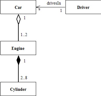
In the simplified example above the class Car represents a car. You can see that the car has one or two engines (rather unusual, but there are examples of two- engined vehicles) and that each engine has two to eight cylinders. The engine is aggregated with the car because you can replace an engine during the lifetime of a car. However, the relation is typically a relatively long-termed one.
The above figure shows that the cylinders are connected with the engine through a composition. This means that the cylinders are a fixed part of the engine and will live as long as the engine (this may not be true in real world engines, but for the sake of simplicity it is in this example).
The driver associates zero to many cars. The car need not know the driver, so the association is a directed association from driver towards car. The association is named drivesIn. The best practice is usually to use directed associations rather than bidirectional associations (associations with no arrows), if it is not obvious in the situation that a bidirectional association is needed.
Between the three types of object relations multiplicity is shown. The multiplicity is used to indicate the number of objects in each end of the relation. The multiplicity can be a single number (like 1 or 2), or it can be an interval (like 0..* or 2..8). While modelling the class diagram the multiplicity is often obvious.
Packages
Packages are collections of classes that are connected.
Packages are UML constructs that are used to organise model elements into groups, making the UML diagrams simpler and easier to understand. Packages can be used to organise any type of UML classifier. Typically, they are used to organise classes and use cases.
Rules of thumb for modelling into packages:
- Classes in the same inheritance hierarchy typically belong in the same package.
- Classes related to one another via compositions or aggregations often, but not always, belong in the same package.
- Classes that collaborate with each other and exchange a lot of information reflected by the sequence diagrams and communication diagrams often belong in the same package.
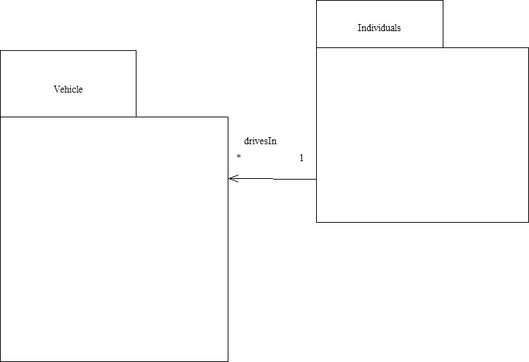
Packages (or strictly speaking the classes in the packages) are interconnected through associations. Below is an example of a package diagram:
Package diagram
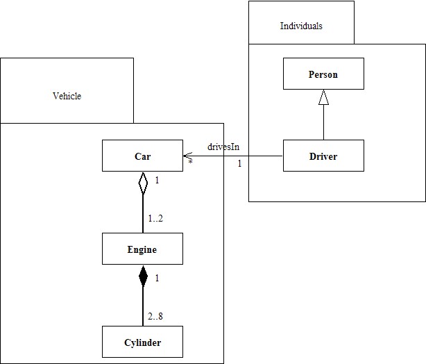
The package diagram above shows two packages: Vehicle and Individuals. If the classes in the packages are drawn, it is easy to see the relations. For projects with a large number of classes, a package diagram can help provide the overview. See the example below:
Package diagram incl. classes
Why
The class diagram is the model of the system. The class diagram shows the relations between the individual parts that the system consists of.
In software systems the class diagram is called the data model. In mixed systems consisting of mechanical, electronic hardware and/or software, the class diagram expresses the total system regardless where the specific class would be realised. The selection of where to implement a specific class is done in the activities General Architecture Design and Selecting the Technical Platform.
Through modelling the class diagram the developer gains knowledge as to how the system should be composed. Modelling the class diagram is a highly iterative process. Very often the developer may ask questions due to missing information about the system-to-be. Then it is often necessary to go back to the previous activities and to the customer to retrieve the necessary information. Consequently, modifications are made in all artefacts, not only in the activities which are closely related to the class diagram modelling.
Example
Inverter: The Inverter class represents the physical inverter that converts DC from the Photovoltaic Cells to AC and feeds the power into the house mains supply. The Physical inverter delivers data about current production. The data is kept in the Inverter Class.
TemperatureSensors: The TemperatureSensors measure the current temperature. In the system there are 5 temperature sensors: IndoorTemperature, OutdoorTemperature, SupplyPipeTemperature, HotWaterTankTemperature and BoilerTemperature.
Burner: The Burner controls the oil burner in the boiler. The boiler temperature should be more than 10 degrees Celsius higher that the expected supply temperature calculated by the BoilerUnit.
BoilerUnit: The BoilerUnit controls the heating in the house by controlling the heating supply pipe temperature. This is done by mixing water from the boiler with water returning from radiators. The BoilerUnit controls the supplied temperature by measuring the indoor, the outdoor and the supplied temperature and by comparing against a pre-set temperature. If the BoilerUnit finds that heating is needed, the heating supply pump should be turned on.
HeatingCirculationPump: The HeatingCirculationPump controls the heating supply circulation pump.
MixerMotor: The MixerMotor turns the mixer motor clockwise to allow more hot water from the boiler to be mixed with the water returning from radiators or counter clockwise to let a greater portion of the water recirculate.
HotWaterCirculationPump: The HotWaterCirculationPump controls the circulation pump for hot water production.
HotWaterElectricHeater: The HotWaterElectricHeater controls the electric heater in the hot water tank. If the boiler and the oil burner are not in operation or there is enough photovoltaic power present, the electric heating of the hot water tank is prioritised.
HotWaterTank: The HotWaterTank controls if the hot water is produced by electric photovoltaic power - if a sufficient amount is present - or by water from the boiler. If there is not enough photovoltaic production and the boiler temperature is higher than 30 degrees, the pump should be switched on when the temperature in the hot water tank is lower than a pre-set limit. If necessary, the boiler temperature should be increased by turning the oil burner on.
Class diagram
In the early phases during analysing a project there are no need for thinking in generalisations, this can be added in the design phase.
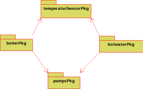
Package Diagram
Tools
A lot of tool are available for the different platforms. For instance on Linux the Dia diagramming tool is typically available for installation. It might look a bit dated, but produces the general diagram fine.
On-line tool are comming up. E.g. draw.io is an example utilising your preferred cloud storage.
Used In
The class diagram showing the Problem Domain is used throughout the rest of the development of the system-to-be. The State Machine Diagrams shows the dynamics of the individual class.
