Difference between revisions of "Block Diagram"
(New page: == What == Designing the block diagram for the system-to-be. Image:tx_oodocs_0526411088.gif == How == '''The dish''' Detailed block diagram design. '''Ingredients''' * E...) |
(Links added) |
||
| Line 1: | Line 1: | ||
| − | |||
== What == | == What == | ||
| Line 14: | Line 13: | ||
'''Ingredients''' | '''Ingredients''' | ||
| − | * Exact | + | * [[Exact Requirements]] (HW timing, etc.) |
| − | * Class | + | * [[Class Diagram]] and a short description |
| − | * State | + | * [[State Machine Diagrams]] |
| − | * Use | + | * [[Use Cases]] |
| − | * Sequence | + | * [[Sequence Diagrams]] expressing the dynamics of the system |
| − | * Function | + | * Results from the [[Function Analysis]] |
| − | * Interface | + | * Results from the [[User Interface Analysis]] for user interface |
| − | * Interface | + | * Results from the [[System Interface Analysis]] |
| − | * Design | + | * [[Design Component Diagram]] |
| − | * Design Criteria | + | * [[Design Criteria]] |
'''Process''' | '''Process''' | ||
| Line 32: | Line 31: | ||
Each block in the block diagram must contain an input and output specification. There are several kinds to choose between. You need to ask if it can be any of the following: | Each block in the block diagram must contain an input and output specification. There are several kinds to choose between. You need to ask if it can be any of the following: | ||
| − | |||
| − | |||
* Power supply input/output: Describe voltages and power consumption for each voltage. | * Power supply input/output: Describe voltages and power consumption for each voltage. | ||
| Line 39: | Line 36: | ||
* Analog signal: describe the specific type and levels. Video, audio, on/off, etc. | * Analog signal: describe the specific type and levels. Video, audio, on/off, etc. | ||
* Digital signal: describe the specific type and levels. | * Digital signal: describe the specific type and levels. | ||
| − | |||
Once you have answered these questions, it will be possible to design each block. | Once you have answered these questions, it will be possible to design each block. | ||
| Line 48: | Line 44: | ||
In order to make it possible for the HW developer to develop each block, the block diagram must contain all connections in order to describe all input and output signals. | In order to make it possible for the HW developer to develop each block, the block diagram must contain all connections in order to describe all input and output signals. | ||
| + | |||
| + | An immediate follow up can be the [[HW Design]]. | ||
Latest revision as of 12:20, 22 September 2009
What
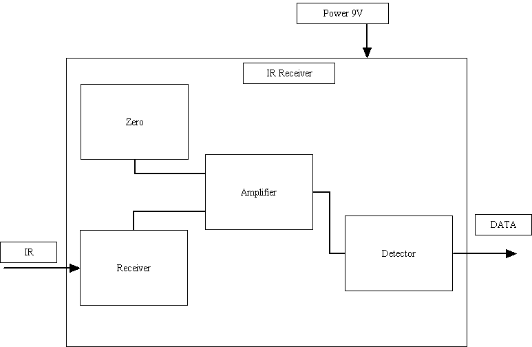
Designing the block diagram for the system-to-be.
How
The dish
Detailed block diagram design.
Ingredients
- Exact Requirements (HW timing, etc.)
- Class Diagram and a short description
- State Machine Diagrams
- Use Cases
- Sequence Diagrams expressing the dynamics of the system
- Results from the Function Analysis
- Results from the User Interface Analysis for user interface
- Results from the System Interface Analysis
- Design Component Diagram
- Design Criteria
Process
From the component diagram, the class diagram and the HW specification you should select which part to implement in HW. Remember each class contains up to 3 parts. A MW, SW and HW part. Focus must be on the HW part.
Now design the HW block diagram.
Each block in the block diagram must contain an input and output specification. There are several kinds to choose between. You need to ask if it can be any of the following:
- Power supply input/output: Describe voltages and power consumption for each voltage.
- Bus: I2C, RS232, Serial, Parallel, etc.
- Analog signal: describe the specific type and levels. Video, audio, on/off, etc.
- Digital signal: describe the specific type and levels.
Once you have answered these questions, it will be possible to design each block.
Why
To make it possible for the HW developers to develop the HW, a block diagram must be made.
In order to make it possible for the HW developer to develop each block, the block diagram must contain all connections in order to describe all input and output signals.
An immediate follow up can be the HW Design.
